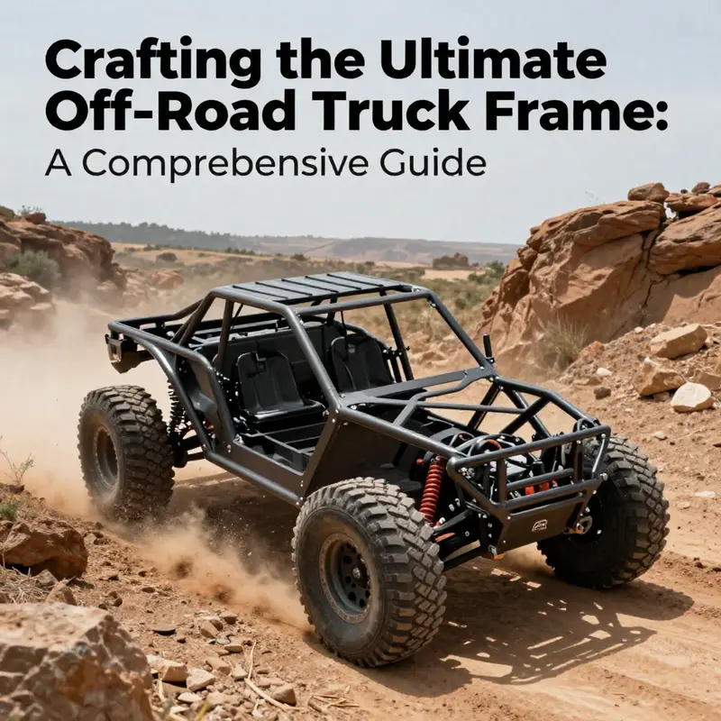
Building an off-road truck frame is not just a construction task; it’s a commitment to adventure, rugged terrains, and the thrill of exploration. Off-road enthusiasts know that the difference between a reliable vehicle and a troublesome one often boils down to its frame. This guide immerses you into the essentials of designing and constructing a durable truck frame, catering to seasoned racers and rugged landowners alike. Through detailed chapters, we will navigate the intricacies of design and planning, material selection, cutting and fabrication techniques, and finally, assembly and welding, ensuring that every crucial step is covered for your off-road experience.
From Blueprint to Backbone: Designing a Rugged Off-Road Truck Frame
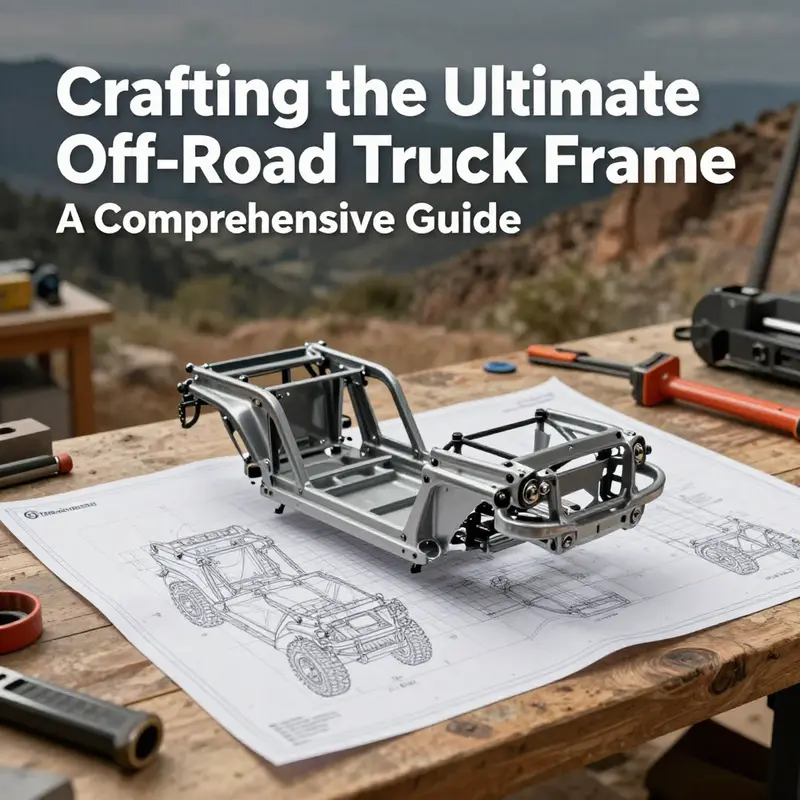
Designing a frame for an off road truck begins with purpose, terrain, and discipline. The frame is the vehicle backbone, transferring engine torque, suspension loads, and obstacle impacts into a controlled response. A robust frame must combine torsional rigidity, predictable flex, and accessible fabrication. The traditional body on frame approach offers a proven baseline for durability and serviceability, with ladder style rails that resist twisting while keeping the body independent from the frame load path. In practice, this means selecting tube material, cross member geometry, and bracing patterns that provide stiffness where loads concentrate, while allowing enough mass to absorb shocks without excessive weight.
Key design elements include the main rails, cross members, engine mounting zones, suspension mounting brackets, and considerations for drivetrain alignment. Tubing in chromoly or high grade steel offers strength to weight advantages, often with outer diameters in the 1.5 to 2 inch range and wall thickness around 0.095 to 0.120 inches for a balance of stiffness and weldability. Surface treatment such as galvanizing or powder coating helps corrosion resistance in muddy, wet, and salty environments.
A well planned frame manages load paths with triangular bracing and gussets at critical joints. The front, mid, and rear sections each see different demands; the engine bay demands stiffness to resist engine torque during launch, the midsection must maintain alignment under suspension articulation, and the rear must stay rigid under axle torque. The geometry also accounts for ground clearance and steering angle, ensuring that tire travel does not cause interference with the frame or protective plates.
Practical steps start with a detailed layout and a bill of materials, followed by a staged fabrication process. Precise cut lengths, checked squareness, and clean welds are essential. TIG welding yields clean consolidated joints on chromoly tubes, while MIG can be used for thicker sections or different alloys, but requires proper heat management to avoid warping. Post weld treatment and careful inspection reduce the risk of hidden cracks after the first test run.
Digital tools complement hands on building. CAD models help predict intersections, clearances, and weight distribution; finite element analysis can identify stress concentrations and allow optimization before metal is cut. Physical testing, including static load tests and controlled off road trials, verifies that the frame behaves as intended under real world conditions. A robust frame design anticipates modular upgrades and easy replacement of components without compromising its structural envelope.
In the end, the frame should feel predictable and forgiving under rough terrain, enabling the driver to focus on control and terrain negotiation rather than fighting the chassis. The design philosophy balances rigidity with weight, serviceability with protection, and traditional engineering principles with modern manufacturing techniques. For builders seeking inspiration, reference open source projects and historical ladder frame discussions to understand how tube geometry, joint detail, and reinforcement strategies influence overall stiffness and reliability.
The Skeleton You Build On: Material Choices that Shape an Off-Road Truck Frame
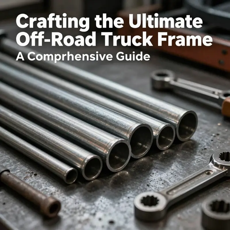
The frame of an off-road truck is more than a skeleton; it is the first line of defense against the brutal realities of rocky climbs, muddy ruts, and long, demanding miles. Every choice, from the metal in the rails to the way those rails are joined, reverberates through handling, durability, and repairability. When you set out to design a frame, you are not just selecting a material; you are choosing a path of performance. The material dictates how much mass you bear, how the frame will twist and absorb shocks, how it will resist corrosion, and how feasible it is to repair in the field or in a shop. In this chapter, we explore the material landscape with a clinician’s eye for safety and a craftsman’s respect for practical constraints. The goal is a frame that remains trustworthy through the long arc of a build, from the first mock-up in CAD to the last test-and-tune session on the toughest terrain.
High-strength steel remains the backbone of most rugged off-road frames. It is the workhorse genre of chassis construction. When the terrain throws its harshest tests—torsional twists, heavy landings, side load during a rock obstacle—the steel frame tends to hold its ground. The strength-to-weight balance is forgiving in the sense that steel can tolerate a wide margin of error in fit-up and welding while still delivering reliable performance. Toughness is its bread and butter; the material can absorb impact energy without fracturing and can resist the kinds of fatigue cycles that many off-road sessions impose. From a fabrication standpoint, steel is more forgiving and more economical than many alternatives, with a robust ecosystem of tubes, fittings, and welding practices that builders rely on for predictable results. For the structural rails themselves, thick-walled chromoly steel is a stalwart option in many designs. Chromoly tubing, such as 1.5 to 2 inches in diameter with wall thickness around 0.120 inches, offers a compelling mix of ductility, weldability, and strength that supports complex roll-cage geometry and aggressive weight-bearing configurations. The practical takeaway is that a steel frame is often the most dependable, especially when the builder’s aim is to endure repeated abuse in real-world off-road environments.
Yet weight is not a mere accounting line item; it shapes how the truck accelerates, climbs, and negotiates the trail. The heavier the frame, the more energy you must push, and the more weight you carry through corners and over obstacles can affect momentum and wheel loading. That is why many builders treat steel as a platform on which innovation can still flourish. The more advanced designs deploy steel where it must bear the most load—rails, crossmembers, mounting points for the engine and suspension components—while exploring weight-saving strategies in non-critical areas or in combination with lighter materials. This is where the concept of a hybrid frame begins to exert its influence. If you need to shave pounds without compromising safety, you can steer toward hybrid strategies that leverage the best of different materials. The central idea is not to chase the lightest frame at any cost but to tailor the weight distribution to the truck’s intended role.
Aluminum alloy opens a different route. It is celebrated for its lightness, typically around 30 percent lighter than steel in equivalent sections. The lighter frame translates to better fuel economy, crisper throttle response, and improved handling—qualities that matter when the vehicle is bouncing through rough terrain or sprinting between checkpoints. Aluminum also offers notable corrosion resistance, which can be vital in wet climates, mud, or salt spray. However, aluminum presents a set of trade-offs that any practical builder must plan for. The most immediate is strength in load-bearing zones. Aluminum alloys, while strong, often do not match steel’s durability under the high-torsion, impact-heavy demands of extreme off-roading unless carefully designed and reinforced. This means aluminum-heavy frames require meticulous engineering to ensure the joints, mounts, and rails do not become weak points after repeated flex. Additionally, aluminum is more challenging to repair after damage; a dent or bend often necessitates specialized equipment and techniques, and field repairs can be more limited than those for steel. For these reasons, aluminum is frequently deployed in a hybrid frame: keep steel where load paths demand robustness, and place aluminum in areas where weight savings yield the most benefit without compromising structural integrity—such as some crossmembers, skin panels, or noncritical supports.
Carbon fiber composite represents a jump toward the upper echelon of performance-oriented construction. It delivers unmatched strength-to-weight ratios and superb rigidity. When a builder seeks to maximize agility, reduce unsprung weight, or optimize fuel economy without sacrificing the ability to withstand mountainous terrain, carbon fiber becomes appealing. Yet carbon fiber is not a universal cure for every off-road frame. Its brittleness under sharp, local impacts can manifest as catastrophic failure if the load path is mismanaged. The repair toolbox for carbon fiber is far more specialized—and far more costly—than for metal. Because of these realities, carbon fiber is typically reserved for specialized or prototype builds, where the engineering team can curate the frame’s responsibilities so carbon fiber carries the loads where it shines and defers others to metal. In practice, carbon fiber often plays a supporting role in the form of exterior panels, crossmembers, or secondary structures, with the core frame rails remaining steel or steel-aluminum hybrids to preserve crashworthiness and repairability.
A modern, well-thought-out approach to materials is rarely black-and-white. The most robust off-road frames adopt a hybrid philosophy that plays to the strengths of each material in the right places. Critical load paths—such as the primary rails, engine and drivetrain mounting points, roll-cage intersections, and high-stress joints—often stay steel or chromoly for resilience and predictable weld quality. In less-stressed zones, or where weight savings deliver meaningful performance benefits, aluminum or even carbon fiber can make sense. The practical purpose of this strategy, beyond raw numbers, is to preserve rigidity and strength while reducing mass in places where the weight is not as consequential to safety and structural integrity.
A well-designed frame also considers fatigue life and environmental exposure. Off-road frames live in a world where moisture, mud, dust, and corrosive elements threaten longevity. Steel frames typically receive protective coatings, galvanizing, or powder finishes to fend off rust. Aluminum’s corrosion resistance helps, but aluminum alloys can suffer galvanic corrosion when paired with steel parts in contact without proper isolation; designers manage this by using compatible fasteners, coatings, or barriers to prevent direct electrical contact. Carbon fiber’s chemical resistance is strong, but its joints require careful attention to moisture sealing and UV protection to avoid degradation. The art of material selection, then, becomes a choreography of compatibility, coating strategies, and maintenance routines that align with the truck’s climate, expected use, and the builder’s willingness to invest in upkeep.
Beyond the choice of base material, the method of fabrication shapes the final performance. Cutting, bending, and welding must respect the material’s behavior. Steel tubes with thick walls might bend differently and require heat management during welding to avoid warping. Aluminum, with its different thermal expansion and heat tolerance, benefits from controlled heat input and sometimes specialized welding techniques to maintain joint integrity. Carbon fiber, while strong, depends on precise layups, resin systems, and cure cycles; even small imperfections can propagate into structural weaknesses. A chassis builder who treats fabrication as an engineering discipline—planning joint geometries, selecting compatible fasteners, and validating with mock-ups in CAD—will achieve a frame that stays straight under load, rather than one that warps or develops unwanted twists over time.
Implementation choices carry a cascade of architectural consequences. For example, the diameter and wall thickness of frame rails, a detail often coated in cautionary numbers in manuals, influence stiffness, weight, and the frame’s ability to distribute shock to maintain wheel contact with the ground. It is not only about strength in a static sense; it is about how the frame transmits loads and absorbs dynamic forces when wheels strike a rock, when a suspension arm introduces a twist, or when the vehicle lands from a jump. The most reliable builders align these choices with a coherent structural narrative: they map load paths, design joints to promote full joint penetration during welding, and test squareness and alignment to guarantee that the frame will hold its geometry under load. In practice, this means scheduling a sequence of steps that starts with a well-thought-out CAD model, moves through precise cut-and-fit work, and culminates in a disciplined welding and post-weld treatment process. The payoff is a frame that breathes with the terrain rather than fighting it, a chassis that keeps the driver and passenger cell protected, and a platform that can be iterated with predictable results as the vehicle moves from a pure concept into a functioning off-road machine.
For builders who want a practical route to balancing these factors, the literature and real-world guides emphasize a few recurring themes. First, define the vehicle’s mission clearly. A rock crawler needs maximal fatigue resistance and robust joints, while a desert racer prioritizes a lighter frame for speed and reliability over long distances. Second, plan a hybrid architecture early in the design process. Placing steel in high-load zones and lighter materials elsewhere yields a frame that can withstand the worst hits and still perform efficiently over long miles. Third, specify welding and fabrication standards that match the material choices. TIG welding for chromoly steel rails gives clean joints with deep penetration; MIG can be acceptable for certain aluminum transitions if the operator employs proper heat control and shielding. Fourth, anticipate maintenance realities. A frame should be inspectable in the field and in a shop, with components that can be replaced or repaired without sending the truck to a specialized facility for every ding. A thoughtful combination of material science and practical engineering makes this possible.
The deeper lesson in material selection is that you are sourcing a performance envelope, not a single number. Strength must be weighed against weight, stiffness against impact tolerance, repairability against corrosion resistance, and cost against manufacturability. The correct material mix emerges when you align physics with purpose. A strong, well-connected frame that balances steel’s durability with aluminum’s lightness, or a steel-dominant frame with carbon fiber panels, can offer a superior baseline for the multifaceted demands of off-road travel. In the end, the frame is the skeleton that lets every other component, from suspension geometry to drivetrain mounting, express its intended character. It is where dreams of speed, control, and resilience meet the realities of terrain and time.
To anchor these ideas in a broader chassis conversation, consider how other builders approach the same problem. Some teams prefer a robust steel ladder-frame with carefully triangulated tubes to maximize torsional stiffness and crash safety. Others adopt a monocoque-like approach, layering high-strength materials in key zones to achieve similar rigidity with less mass. Still others experiment with hybrid rails where steel carries the critical load path while aluminum or carbon fiber lightens adjacent sections. Each path has its own calculation of benefits, constraints, and maintenance needs. The thread that unites them is the fundamental truth: the material choice is a design decision, not a afterthought. It shapes how the frame behaves when the trail gets brutal, how easy it is to build, how much weight you carry in total, and how readily you can repair or modify the machine when the next challenge arises.
For readers seeking a broader practical anchor, this discussion sits alongside practical case studies and fabrication roadmaps that remind us to couple theory with trench-level execution. As you digest these material options, a useful mindset is to treat the frame as a living part of the vehicle’s performance envelope. Materials influence the frame’s stiffness under load, the way heat affects joints during welding and use, and the overall durability that governs long-term serviceableness. The decision to use a hybrid approach—steel in critical stress zones with aluminum or carbon fiber in others—emerges as a balanced path that respects both the physics of load paths and the realities of manufacturing. Whether you are planning a rock crawler intended for brutal obstacles or a cross-country runner designed for long, punishing miles, the material strategy you choose will echo through every corner, every climb, and every mile of the journey ahead.
Guidance from related chassis work can illuminate this path. For practical context in chassis work, see Mastering Diesel Mechanics: A Step-by-Step Path to Success. This internal reference complements the structural discussion by grounding the conversation in the broader discipline of heavy-vehicle maintenance and rebuild practices, where materials, joints, and load paths also determine the reliability of the machine in demanding conditions. While the focus here remains on the frame, the overarching principle—the marriage of material behavior with real-world use—runs through both domains. Understanding this relationship helps builders anticipate how a given material choice will perform not only in the lab or the CAD room but out on the trail, where the frame must survive, adapt, and endure.
External research on frame materials reinforces the practical perspective described here. When you cross the threshold from theory to field-ready design, you are invited to consult broader resources that synthesize strength, weight, and safety. As a reference point for the physics of frame materials and their impact on safety and performance, see Frame Materials Explained. This external link offers a concise synthesis of how different materials perform under the duress of real-world driving, helping you connect the design choices you make in your shop with the outcomes you want on the trail.
Internal Link: Mastering Diesel Mechanics: A Step-by-Step Path to Success. Mastering Diesel Mechanics: A Step-by-Step Path to Success
External Resource: Frame Materials Explained. https://www.caranddriver.com/features/a48759317/frame-materials-explained/
Rough-Cut to Rock-Solid: Precision Cutting and Fabrication for an Off-Road Truck Frame
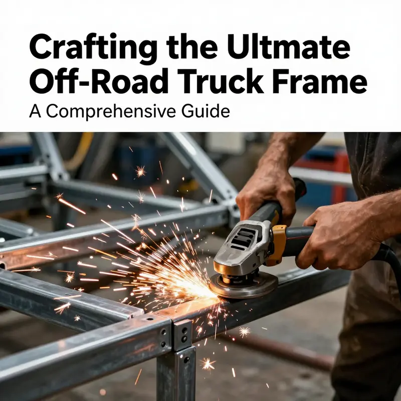
The frame of an off-road truck is more than a sturdy skeleton; it is the living, breathing core that absorbs impact, channels torque, and keeps the vehicle true under extreme conditions. Building it starts with a clear sense of purpose and ends with a rigid, predictable platform that can cradle suspension, drivetrain, and safety systems without bending into the first rut. In between lies a careful choreography of material selection, cutting precision, and disciplined fabrication. Each choice—what steel to pick, how to cut it, and how to fuse it—resonates through every corner of the build as the frame meets the rocks, the ruts, and the weight of the crew and gear borne by it. The journey from raw stock to a complete, tested chassis hinges on harmonizing strength, stiffness, and predictable behavior, so that dynamic loads from suspension articulation and torsional twists do not awaken hidden weaknesses or sudden misalignment. That harmony is not accidental; it is earned through deliberate decisions in material science, cutting technique, and welding practice that together define the frame’s life in the harsh world of off-road performance.
Material selection sits at the very heart of this process. High-strength steels such as chromoly and specialty alloys offer tensile strength and resilience that ordinary mild steels cannot sustain. Chromoly, particularly 4130-type alloys, delivers an excellent strength-to-weight ratio and a robust resistance to deformation when exposed to repeated shocks and high torsional loads. Alternatives like ASTM A572 Grade 50 provide a reliable baseline with generous ductility and good weldability, which can be advantageous for larger frame components or sections where flexibility enhances overall behavior under load. The choice depends on the frame geometry, expected duty cycle, and the weight budget. The thickness of the tubing matters as well: thick-walled sections resist bending and twisting, yet they demand careful heat management during fabrication to avoid cracking or warping. Importantly, the material selection sets the stage for how cutting and welding will perform. For example, 4130 chromoly responds exceptionally well to TIG welding when joints are prepared with clean edge preparation and proper fit-up, helping to achieve full joint penetration without compromising the tube’s integrity. By contrast, thicker plates or portions of the frame that experience severe impact may benefit from a more forgiving alloy like A572, where the welds are easier to manage and the risk of cold cracking is reduced.
Cutting, the first physical transformation of the frame, is where precision and control are essential. Modern fabrication embraces a triad of techniques—plasma cutting, oxy-fuel cutting, and CNC laser cutting—each with its own strengths and trade-offs. Plasma cutting shines when working through thick steel plates and producing fast, clean cuts with a relatively forgiving setup. It is well suited to rough-cutting large sections of the bottom chassis or lightening holes that don’t require near-micrometer tolerances. Oxy-fuel cutting remains practical for extremely thick sections or situations where plasma equipment is not available, but it introduces a heat-affected zone that can alter properties near the cut if not carefully managed. The heat-affected zone is not just a cosmetic concern; it can influence residual stress and, if left unchecked, contribute to distortion during subsequent welding.
CNC laser cutting stands at the high end of precision. It delivers the finest tolerances and repeatability, which matters when fabricating complex frame geometries, mounting brackets, and gussets that must mate cleanly with tubes and plates. The laser approach minimizes edge warping and produces consistently straight cuts that reduce the time spent on fit-up during assembly. The choice among these methods is not solely about money or speed; it is a calculus of tolerances, material thickness, and the geometry of the parts being produced. In practice, an experienced builder often uses a combination: laser-cut critical brackets and joints, plasma-cut large panels, and oxy-fuel for very thick sections where cutting with other means would be impractical. As with many manufacturing decisions, the goal is to minimize distortion and maximize repeatability, so the parts assemble with predictable gaps, true angles, and consistent weld sequences.
Across all cutting methods, the importance of dimensional accuracy cannot be overstated. The frame relies on precise alignment of tubes and brackets to ensure the suspension geometry remains within design tolerances and that steering, drivetrain, and safety devices align correctly. Even small deviations—half a millimeter here, a degree of twist there—can compound during welding, producing a frame that is momentarily out of square or misaligned at key joints. This is where the role of fixtures and jigs becomes central. Builders often develop custom fixtures that hold tubes in exact positions, with pins that ensure repeatable intersection angles. The fixtures act as a physical memory of the design, guiding each tube into its intended location with the same geometry every time. When cutting is complete, a careful fit-up check becomes a ritual: dry-fit the sections on a flat, level surface, verify squareness with accurate gauges, and confirm that the assembly will nest into engine mounts, suspension mounts, and crossmembers without forcing or grinding. Only after the parts meet the fit-up criteria should welding begin.
Welding, the core act of turning cut stock into a single, rigid frame, demands more than raw power with a torch. TIG welding has become the preferred method for off-road frame construction, particularly when working with thin-walled chromoly tubing and high-strength alloys. The beauty of TIG lies in its control; it yields clean, narrow beads with deep penetration when properly executed. TIG welding requires steady setup, precise torch handling, and a good shielding gas regime to prevent oxidation and poor fusion. It is slower than other methods, but the payoff is a consistently high-quality weld that preserves the alloy’s mechanical properties and minimizes heat input that could warp tubes. MIG welding remains a valuable tool where speed is essential or where heavier sections require robust continuity. It can fuse thicker walls efficiently, but it may demand more post-weld cleanup and sometimes more post-weld heat treatment to relieve residual stresses. Regardless of the method, the preparation is non-negotiable. Joints must be clean, edge preparation uniform, and fit-up gaps tight enough to ensure full penetration without excessive filler metal. Proper technique—angle control, travel speed, and heat input—reduces the risk of porosity, cracking, and undercutting that can undermine joint strength.
Post-weld care is as critical as the weld itself. Most seasoned builders will incorporate a post-weld heat treatment or stress-relieving cycle for complex frames. Stress relief helps reduce residual stresses from the weld process and can dramatically improve fatigue life under the repeated shock loading characteristic of off-road driving. The finishing stage follows the heat treatment, where weld beads are ground smooth to prevent stress risers and to improve overall aesthetics and corrosion resistance. A carefully executed finish also makes inspection and maintenance easier, as surface imperfections and cracks become more readily visible. The final surface treatment—sandblasting to remove oxides and scale, followed by powder coating or a quality paint job—does more than confer looks. It protects the frame from the harsh elements that off-road life invites, including mud, water, and abrasive dust. A robust finish reduces the rate of corrosion, maintains structural integrity, and helps ensure that the frame remains easy to inspect for cracks, corrosion, or signs of wear.
Quality control weaves through every stage of cutting and fabrication. It begins with CAD-driven dimensional verification, a practice that translates the designed geometry into real-world parts with traceable tolerances. Alignment checks ensure the frame remains square and true as sections are welded together. During assembly, a combination of load testing and vibration analysis can reveal weaknesses that might not be evident through visual inspection alone. The goal is a frame that can tolerate the dynamic demands of off-road terrain, including torsional twists, lateral forces, and repeated impacts. In practice, this means not only looking for obvious defects like cracks and porosity but also validating how the frame behaves under simulated real-world loads. The expectation is that the frame remains rigid, with minimal flex in critical areas, and that joints and brackets perform consistently over time. The craftsmanship demanded by this process is not merely about strength; it is about predictability and reliability when the vehicle is pushed to its limits.
In the broader scope of the build, cutting and fabrication are inseparable from the vehicle’s overall architecture. The frame must accommodate the engine, drivetrain, and suspension while preserving the geometry that makes the vehicle handle terrain with confidence. This means that every cut, bend, and weld has to serve a larger design intent. The bottom chassis, for instance, is typically fabricated from heavy tubing designed to resist bending while supporting the weight of components and passengers. Front, mid, and rear support structures must integrate seamlessly with crossmembers and safety features like a roll cage, all while preserving legroom and driver protection through side protection bends that result from continuous bent tubes. The process is iterative; designers may refine tube routes or modify gusset placements as they test fit suspension arms or engine mounting points. The best builders embrace this feedback loop, documenting deviations and incorporating adjustments in the next build or revision so that future projects begin with improved accuracy and fewer surprises.
For those who want a practical, step-by-step perspective on the fusion of cutting and fabrication with broader vehicle performance, a broader discussion on precision in welding and fabrication can be found in related resources. A related journey through precision and integration in a similar mechanical domain can be explored in mastering-diesel-mechanics-your-step-by-step-path-to-success, which offers insights into how precision processes intersect with drivetrain assembly and maintenance. This internal reference helps connect the dots between the frame’s structural integrity and how it supports the powertrain and suspension system in real-world use. mastering-diesel-mechanics-your-step-by-step-path-to-success
The culmination of cutting and fabrication is not merely a rigid frame but a frame that behaves consistently under load, with predictable twists and a known response to steering, braking, and suspension inputs. The rider’s safety and confidence rest on the frame’s ability to return to its intended geometry after every bump, every rock strike, and every sharp turn. The best frames do not surprise the operator; they deliver a measured, linear response that allows the driver to place the vehicle with precision where it matters most. In practice, this means the frame is designed with stiffness in key planes, the joints are welded with clean penetration, and the finished product has a durable, corrosion-resistant surface that remains legible to the eye for crack development. It also means the builder recognizes limits and plans for inspection cycles, scheduled maintenance, and, crucially, the possibility of future upgrades. The frame should be adaptable enough to accommodate new suspensions, different engine configurations, or revised safety standards without a complete rebuild.
In sum, the cutting and fabrication phase of building an off-road truck frame is where theory meets practice. It translates design intent into a tangible mat of tubes and brackets whose every dimension is vital to overall performance. It demands a blend of material science, precision cutting, controlled welding, and disciplined quality assurance. It requires a mindset that values fit and finish as much as strength and function. And it rewards those who treat every joint as a potential point of failure to be managed with care, not a mere place to save time or money. When done well, the frame becomes the trustworthy backbone that carries not only the vehicle but the expectations of the driver who trusts it to handle the toughest terrain, mile after mile, without breaking contact with the earth or surrendering safety. The road from rough-cut stock to rock-solid chassis is a journey of disciplined technique, exacting standards, and an unwavering commitment to precision. It is the quiet testament to the craft of building an off-road machine that can endure the unpredictable theatre of off-road adventure while delivering predictable, confidence-inspiring performance in every rock garden, dune field, or muddy hill climb.
External resources can provide a broader, hands-on walk-through of the steps involved and the practical pitfalls to avoid as you translate this theory into a finished frame. For a practical, step-by-step walkthrough, see the external guide that maps out the process of building an off-road truck frame in a detailed, applied context: External step-by-step guide.
Welding the Backbone: Precision Assembly for a Rugged Off-Road Truck Frame
The moment a designer’s blueprint becomes a tangible frame, the true art and risk of building an off-road truck begin. The frame is not a cosmetic feature; it is the structural backbone that must endure rock ledges, mud, mud-slinging torque, and the ever-shifting loads of a suspension system bearing down on uneven terrain. Precision in this stage determines everything from handling to safety. Much of that precision comes down to two intertwined crafts: cutting and beveling with exacting standards, and welding with a disciplined sequence that controls heat, alignment, and fitment. When you work with chromoly tubing in the 1.5 to 2 inch range and a wall thickness around 0.120 inches, you are choosing a material that rewards meticulous preparation and punishes careless heat. The goal is a frame that remains square under load, distributes stress evenly, and resists fatigue far longer than a budget alternative. The design intent meets the shop floor at the welding table, and the quality of that meeting sets the vehicle’s fate on the trail.
Cutting the frame rails to length is only the first act; the angles at which those rails join determine how free the frame will be to carry loads and how well it will resist twisting under pressure. Precision cutting means more than straight lines. Each rail must enter the joint with a match in angle and offset. Even small deviations can add up when you’re aligning crossmembers, motor mounts, and knee-braces. Beveling edges becomes the next critical step. The bevel angle is a tool of deep penetration, which ensures the root weld fuses all metal surfaces thoroughly rather than merely sitting on top. A commonly used bevel is in the range of 30 to 37 degrees, chosen to optimize fusion without excessive heat input that could warp tubing. Beveling also helps create a more continuous weld pool, reducing the likelihood of cold starts and gaps that could later become cracks under the dynamic loads of rock crawling or desert runs. After beveling, deburring the edges eliminates burrs and oxide pockets that would trap hydrogen or introduce porosity into the weld. The cleaner the edge, the cleaner the weld, and the longer the frame will last under stress.
Alignment is the invisible but decisive force guiding the whole process. Before any permanent weld is applied, components are tacked together in a controlled environment. Tacking serves as a test fit, locking the pieces in place with minimal heat, so a frame can be maneuvered without shifting. It is a step that many beginners overlook or rush, and the consequence is misalignment that becomes evident only after the welds are laid and the parts are moved into assembly. With the rails tacked, the frame is checked for squareness, levelness, and symmetry across the length of the chassis. Any deviation is corrected at this stage; otherwise, it will echo through every subsequent weld, pulling at joints and forcing misalignment of crossmembers, side protection bends, or reinforcement bars. Once the basic skeleton is aligned, the actual welding begins in a deliberate sequence that manages heat input, minimizes distortion, and preserves the geometry that was verified during the fit-up.
Welding technique is the daily craft that translates plan into permanence. The choice between MIG and TIG welding often comes down to the material and the required fidelity of the joints. Chromoly steel tubing, especially in thicker walls and larger diameters, generally benefits from TIG welding for critical joints because it offers superior control of heat input and penetration. However, MIG welding can be effective if performed with the right wire, shielding gas, and technique, particularly on simpler welds or when speed matters in a production setting. The root pass is where the fusion starts, and it must penetrate deeply enough to fuse all surfaces without leaving a tunnel or cold spot. A root pass may be followed by a cap pass that builds up the surface and creates the flush, uniform weld bead you want both for aesthetic refinements and for structural integrity. In any case, the welder must avoid stopping and starting repeatedly at the same location, which can accumulate heat and cause a soft spot or micro-cracks. Instead, a planned sequence—moving from joint to joint in a logical order—helps distribute heat evenly along the frame and reduces distortion.
Heat management is not an afterthought but a fundamental element of frame welding. The heat-affected zone (HAZ) around each weld can become a source of weakness if it is allowed to grow too large or is subjected to rapid cooling. Some shops mitigate this with controlled preheating of tubing sections, especially chromoly, to reduce the risk of cracking. Interpass temperature control, where you allow a weld to cool only to a specific level before laying the next pass, further minimizes residual stresses. For highly complex chassis with multiple non-linear welds, some facilities employ staged welding sequences and even heat treatment after critical sections are completed. Although heat treatment is not a universal requirement for every frame, in high-performance builds where the frame is expected to endure extreme loads, a stress-relief cycle can make a noticeable difference in long-term fatigue life.
In the modern shop, robotic welding arms with articulated joints are becoming the norm, especially for complex chassis geometries common in off-road performance frames. These systems can handle tight spaces and non-linear weld paths with a repeatability that far exceeds manual welding. They also reduce the welder’s exposure to fumes and heat, while maintaining a consistent quality across repeated sections. The precision of robotic welds is particularly valuable when the frame includes integrated features such as center-reinforcement ribs or diagonal braces that must crystalize into a single, continuous weld bead. Even when human welders are at the helm for the most critical joints, robotics can handle the bulk of the repetitive, high-precision work, allowing skilled technicians to focus on root and fill passes that demand nuanced control.
Fixturing is the unsung hero that makes all of this feasible. A flat, level work surface is the stage on which the frame will prove its worth. Jigs, fixtures, and clamps hold tubing precisely in place while heat is introduced and stress is redistributed. Every joint requires consistent gaps and alignment so the final weld bead can unify the pieces without creating gaps or misfits that would undermine rigidity. Clamps need to be chosen for the kind of joint being welded—some clamps push pieces tightly together, others maintain a tiny, deliberate gap to ensure adequate fusion. The more stable the fixture, the less time you spend chasing stray heat, correcting drift, or dealing with a misalignment that surfaces only after the frame has cooled and been moved into the next stage of assembly.
After welding, finishing work becomes the bridge between a robust skeleton and a functional vehicle. Grind lines are smoothed, but not to the point of removing the crown that indicates proper fusion; rather, they are finished to reduce snag hazards and to prepare the surface for protective coatings. Welds are inspected for cracks, porosity, and full penetration. If any joint shows signs of porosity or incomplete fusion, it must be repaired with a carefully chosen sequence of preheating, re-welding, and post-weld cleaning. Non-destructive testing methods such as dye penetrant or magnetic particle inspection may be employed for critical joints where any hint of discontinuity would be unacceptable; this is often the case for crossmembers that bear the brunt of torsional loads or for joints near the engine cradle that experience high heat and vibration during operation.
Design integration for an electric propulsion future adds another layer to the welding discipline. As frames evolve to house battery compartments, motor mounts, and dedicated cooling channels, welds must not only be strong but strategically located to avoid heat concentration near battery cells and to preserve space for thermal management equipment. The frame becomes a structural itinerary, a concrete path where powertrain architecture, weight distribution, and crash resistance must be balanced across joint locations. Bracing and reinforcement near motor mounts may need extra beads or alternate welding sequences to ensure those anchors remain rigid even as the powertrain transmits sudden torque during off-camber terrain. In this sense, the frame is more than a passive scaffold; it is an active participant in the vehicle’s performance envelope, shaping how efficient a chassis can be under load and how predictably it behaves when the going gets rough.
The practical flow of building a frame, then, unfolds like a careful choreography. It starts with a precise cut and bevel, then a staged tack-up to test fit and alignment. The main welds follow in a controlled parade—root passes to establish fusion, subsequent passes to build strength, and a final contour pass to smooth and seal. Distortion management, meticulous fixture work, and disciplined heat control keep the chassis true to its intended geometry. Even in a best-case scenario, you expect minor adjustments after the frame has cooled and once the first components—engine cradle, front and rear crossmembers, and side rails—are mounted. A frame that meets its alignment checks early saves hours of rework later when components must be reinstalled or when steering and suspension clearances must be verified.
As you prepare to install the engine, suspension, and drivetrain, the frame should already reflect a holistic understanding of how the car will move. That means the welding sequence and the final weld profiles should not compromise the largest crossmembers or the critical safety features like the roll cage and side protection bends. The continuous welds must carry through joints without abrupt changes in volume, and the surface finish should allow a uniform coat of corrosion protection that will endure off-road weather and moisture. In short, welding the backbone is not simply about sticking metal together; it is about shaping a living, durable structure that can absorb impact, maintain alignment, and transfer energy safely through the chassis whenever the going gets tough. For a deeper technical dive that ties these principles to practical frame geometry, see a detailed guide on off-road buggy frames and their key specifications.
For a practical reference that connects these welding principles with broader frame design considerations, consider exploring a comprehensive guide to off-road buggy frames, which covers specifications, features, and common uses. This resource offers visual demonstrations of how frame geometry supports weight distribution and safety under extreme conditions, and it complements the hands-on practices described here. Mastering diesel mechanics: your step-by-step path to success provides additional context on how drivetrain integration influences chassis design and how careful welding supports reliable power delivery in demanding environments.
In the end, the essence of assembling and welding an off-road truck frame is not only about achieving a perfectly straight instrument of steel. It is about creating a robust, predictable platform that can withstand the unpredictable demands of extreme terrain. It requires a mindset that values precision over speed, heat control over convenience, and alignment over improvisation. It is this mindset that distinguishes a frame that merely holds parts from a frame that truly performs when the tires bite into rock, when suspension articulation climbs through a steep grade, and when a line is carved across a desert wash at speed. The techniques described—precise cutting and beveling, careful tack-up, sequential and controlled welding, robotic assistance where appropriate, and diligent post-weld inspection—form a discipline that every serious off-road builder should internalize. They are the tools that convert a design into a chassis capable of carrying a vision into the wild, confidently and safely.
External reference for further technical context and best practices in frame construction can be found here: https://www.offroadbuggyparts.com/guide-to-off-road-buggy-frames
Final thoughts
Constructing a robust off-road truck frame is a multifaceted journey that demands precision, quality materials, and expert techniques. With careful planning, the right choices in design, and adept craftsmanship in cutting and welding, you can create a vehicle ready to conquer the wildest terrains. Embrace the adventure with a frame that reflects your dedication and passion for off-roading. Remember, the journey does not end with the frame; it continues with exploring the great outdoors.