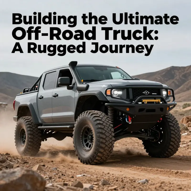
For off-road enthusiasts, creating a custom truck isn’t just a project—it’s a passionate journey toward adventure. Whether you’re seeking to conquer desert dunes or tackle muddy trails, your vision shapes the build. This guide lays out every step, from conceptualizing your dream truck to fine-tuning its performance. You will learn how to define your purpose, source materials, and craft vital components such as the chassis, suspension, powertrain, and wheels to create a reliable vehicle worthy of any terrain. Embark on this rugged expedition and transform your off-road aspirations into reality!
From Vision to Blueprint: Defining Purpose and Drafting the Detailed Plan for Your Off-Road Truck
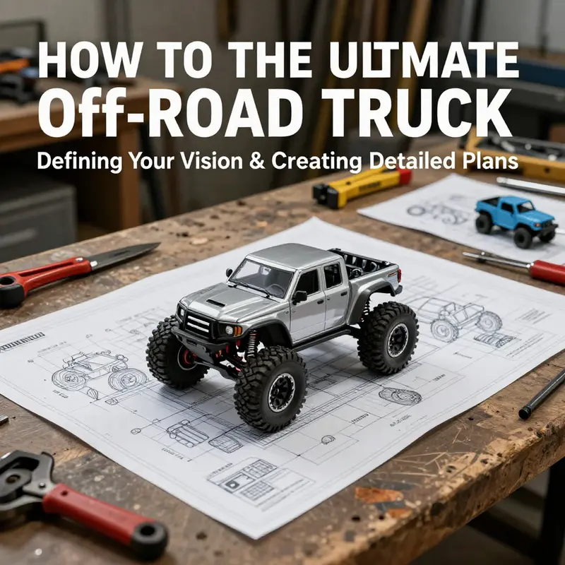
The decision to build an off-road truck begins not with a pile of parts but with a clear purpose and a plan that keeps the project honest from the first sketch to the final test. The path is long and demanding, and the stakes rise with every choice you make about weight, strength, and control. A well-defined vision acts as a north star, guiding every decision about suspension travel, engine torque, and chassis geometry. Without it, the project risks spiraling into scope creep, mounting costs, and a vehicle that excels in theory but falters in reality. The chapter that follows treats this critical starting point as more than a moment of inspiration; it treats it as a rigorous discipline, one that blends practical constraints with ambitious intent and translates them into a living blueprint you can trust on the trail and in the shop.
Begin with a blunt, honest assessment of the terrain you intend to conquer and the performance you deem essential. Will the truck be a rock crawler, crawling over boulders with deliberate control and extreme articulation? Or is it a desert racer built for long, fast runs across arid flats, where reliability over miles matters as much as speed? Perhaps it will live as a trail rig, a versatile platform that handles muddy sectors, sharp climbs, and occasional highway trips with equal aplomb. Each path imposes its own physics on the design: rock crawling rewards low gearing, high torque, and a chassis that tolerates torsion; desert racing rewards high-tower stability, durable cooling, and suspension tuned for speed over rough flat surfaces. Clarifying this purpose early sharpens every subsequent decision about frame construction, steering geometry, and tire selection. It also frames your budget and schedule. If you want a vehicle that can do it all, you will need to describe the limits of that ambition and budget accordingly so the plan remains realistic and deliverable.
With purpose established, you move into the drafting room where the plan becomes tangible. The engine of the project is not the engine in the truck, but the blueprint that sits on the table and in the CAD files. The aim is to capture a chassis layout, suspension geometry, engine placement, and weight distribution in precise terms. The frame, or chassis, is the skeleton of the build, and its integrity governs safety and long-term reliability under the stress of harsh terrain and aggressive driving. A typical approach centers on high-strength steel tubing for the bones of the frame, with selective use of aluminum to shed weight where the structure can tolerate it without sacrificing strength. The geometry must anticipate the forces of landing from gaps, twisting over rocks, and carrying weight through slopes. Planning for these demands up front reduces the risk of a frame that looks good on a drawing but buckles under load.
The planning stage naturally leads to a careful selection of components that must harmonize with the intended use. The powertrain, for example, becomes a dialogue between torque delivery and reliability. A robust engine with ample torque is essential for pulling through tough sections or starting motion on an incline, but it must be matched with a drivetrain that can handle torque without overheating. This is where the drivetrain layout, transfer case, and gear ratios enter the conversation; a four-wheel-drive system with a thoughtfully chosen transfer case and locking differentials can provide the traction needed when one wheel loses grip. The suspension cannot be an afterthought. It has to be capable of long travel and precise tuning to maintain contact with uneven ground. Whether you lean toward independent suspension or a solid axle depends on the terrain profile and the level of durability you require. Each choice comes with trade-offs in ride quality, articulation, weight, and ease of maintenance, and the blueprint must weigh those trade-offs against the vision to keep the project coherent.
Documenting the plan means translating ideas into measurable parameters. The chassis dimensions must be published as exact figures—coordinates for mounting points, crossmember spacing, and the line of the frame rails. Suspension geometry needs a clear map of travel, control arm lengths, toe and camber targets, and the positions that will keep wheels aligned throughout aggressive articulation. Engine placement demands careful consideration of weight distribution, cooling airflow, air intake routing, and accessibility for maintenance. Drivetrain layout requires clear paths for driveshafts, a reliable transfer mechanism, and space for shielded, heat-resistant exhaust routing. The plan should also address the electrical backbone, including a rugged battery installation, a wiring harness route, fusing strategies, and the precise location of gauges and control switches. The goal is not to predict every contingency but to create a framework that can be tested, adjusted, and validated through iterative cycles.
To move from concept to a workable blueprint, many builders turn to computer-aided design tools. CAD modeling enables you to validate fitment, visualize clearances, and stress-test geometry before a single bolt is welded. The beauty of this approach is that it makes potential clashes visible early, reducing costly trial-and-error during fabrication. Yet CAD is not a substitute for real-world reasoning. It should be paired with practical checks: can you access critical components for service, are there safe paths for exhaust and wiring, and will the frame accommodate a stable center of gravity under load? A well-rounded plan balances digital precision with hands-on feasibility. It also foresees the later stages of fabrication, such as jig work, cutting, and welding, ensuring that the frame can be constructed with the available tools and skill set.
As the blueprints mature, the plan specifies how you will source or fabricate major sections. The frame becomes the skeleton through which every other system threads. Attending to the frame at this stage avoids the common pitfall of discovering later that a suspension mounting point conflicts with a steering rack or that a driveshaft interferes with a crossmember. The process highlights the importance of an early procurement strategy: confirm the compatibility of the chassis with a robust engine family, a reliable four-wheel-drive arrangement, and a drivetrain that can distribute torque evenly to all four wheels when traction is uncertain. It is precisely here that the discipline of planning pays dividends. You are not simply assembling parts; you are aligning forces, leverages, and paths of energy so that the entire machine acts as a single, purposeful system.
In this context, it is customary to temper ambition with prudent milestones. Break the build into phases: design validation, basic frame construction, subsystem mockups, and eventually full integration. Each phase yields learnings that feed back into the next, enabling you to refine geometry, adjust component choices, and reallocate resources. The blueprint should reflect those learnings, becoming more robust with each iteration. The goal is not perfection on the first pass but clarity about what must be built, what can be adapted, and what must be abandoned to stay on track. This mindset—iterative, data-informed, and safety-conscious—keeps a demanding project like an off-road truck comprehensible and controllable.
If you want a deeper dive into engine fundamentals and mechanical mastery that supports this planning phase, consider resources such as Mastering Diesel Mechanics: Your Step-by-Step Path to Success. This kind of exploration can sharpen your sense of how engines, cooling, and air intake interact with the rest of the system, influencing decisions about torque curves, air passages, and heat management. Mastering Diesel Mechanics: Your Step-by-Step Path to Success.
The blueprint you forge now must also respect the realities of time, money, and safety. Building an off-road truck is not a weekend hobby; it is a long-term commitment that can demand tens of thousands of dollars and months or years of work. The most cost-effective path pairs a clear vision with a disciplined planning cadence. It involves honest risk assessment, contingency budgeting, and a readiness to scale back ambitions if the plan proves infeasible within the available resources. If you are new to this kind of project, you may choose to begin with smaller exercises—like a dedicated suspension test rig or a chassis mock-up using inexpensive materials. Those exercises act as precursors to the real build, giving you practical experience and a clearer sense of how to translate the blueprint into fabrications, fittings, and assemblies.
Ultimately, the chapter that begins with a vision and a plan closes the loop with a practical, living document. It is a dynamic blueprint that guides your decisions, helps you anticipate challenges, and frames how you will measure progress. It anchors your choices in the terrain you intend to conquer, the load your truck must bear, and the performance you expect in exchange for the time and resources you invest. It invites you to test ideas early, reject what does not work, and embrace what shows promise. And as you move from drafting the plan to shaping metal, remember that the quality of your beginning determines the ease of your journey ahead. The road to an off-road truck is rarely straight, but with a well-defined vision and a detailed, adaptable plan, that road becomes navigable, guideable, and almost inviting. The next stage—sourcing parts and assembling the core systems—will then unfold as a continuation of that deliberate, principled approach, preserving the integrity and safety you established at the outset. External reference: https://www.nhtsa.gov
The Backbone Dilemma: Sourcing or Forging the Chassis for an Off-Road Truck
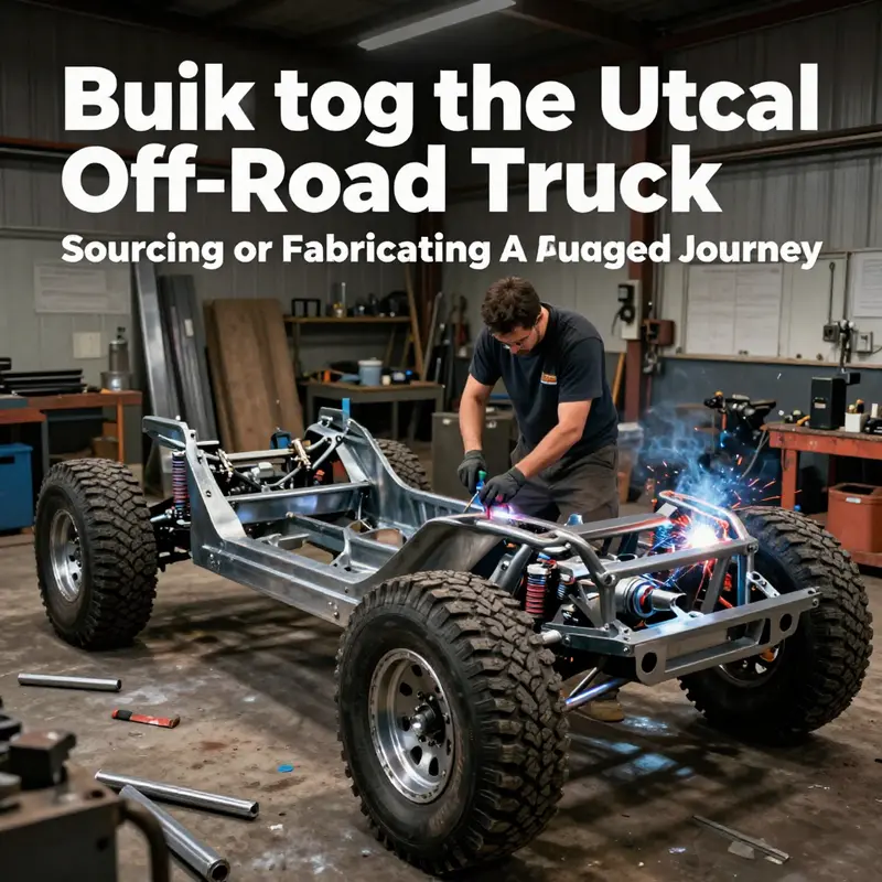
The chassis is the quiet backbone of any off-road build, the unseen skeleton that must endure twists, torsion, rocks, and long, punishing descents. It dictates how all other systems behave under stress, from how a suspension can move to how a powertrain aligns with steering geometry. Because it anchors every other decision, the choice between sourcing a pre-built chassis and fabricating your own becomes the single most consequential fork in the road for an off-road truck. The decision isn’t simply about cost or time; it’s about control, safety, and the relationship between weight, strength, and capability. In this chapter we explore that choice in a cohesive arc, tying the idea of the chassis directly to the overall goal of building a truck that can survive and thrive off the beaten path without losing reliability or safety in the process. The discussion remains grounded in practical realities: planning, material behavior under load, and the careful alignment of power, suspension, and chassis geometry to the terrains you intend to conquer.
When you begin with the chassis, you’re deciding the frame around which every other system will bend. If your vision favors extreme rock crawling, you’ll need a frame that tolerates dramatic articulation, with reinforced joints and a geometry that favors stability in uneven rock inflection. If you’re chasing high-desert speed, the chassis must be light enough to propel quickly yet rigid enough to resist flex under aerodynamic loads and high-speed ruts. For mud and trail duty, hooks and mounts must endure mud adhesion, heat from braking, and frequent impact. These broad intents influence not only materials but also fundamental decisions about wheelbase, track width, and the type of suspension that can be integrated effectively. The chassis is not a passive backbone; it is an active design problem that shapes weight distribution, steering geometry, and even the mounting points for the powertrain. In other words, the chassis writes the first line of the vehicle’s operating rules, and every subsequent choice must respect those rules.
Sourcing a pre-built chassis can dramatically compress development time and reduce risk. A purpose-built, OEM-style bare chassis offers a known starting point with verified structural integrity and a proven track record under demanding conditions. For operators who need reliability, scalability, and a clear compliance path, a certified chassis can streamline the entire build—from aligning mounting points for the body to ensuring compatibility with the chosen powertrain and drivetrain architecture. The advantage here is not just a shorter build schedule; it’s a defined baseline for safety margins, fatigue limits, and load paths. It also often translates into easier coordination with body manufacturers and component suppliers, a factor that matters when you’re aligning industrial-grade engines, heavy-duty suspensions, and complex steering systems in a single vehicle. Of course, the premium price tag and less flexibility in layout are part of the equation. If your mission profile is industrial or commercial—where uptime, repeatability, and serviceability trump bespoke elegance—a sourced chassis can be the pragmatic choice.
Fabricating your own chassis, by contrast, is a doorway to total design freedom. It invites you to optimize weight balance, wheelbase, and frame stiffness for your exact terrain and payload. Yet freedom comes with responsibility. Fabrication demands a solid foundation in metalworking, welding, and structural analysis, plus access to a workshop equipped for precise cutting, bending, and welding. Planning begins in a CAD environment where you map out the chassis geometry, the triangulation of rails, cross-members, and the exact mounting points for the suspension, engine, transmission, and transfer case. CAD lets you play with weight distribution, test how changes in wheelbase alter approach and departure angles, and forecast how the frame will behave under torsion when the vehicle launches off a rock ledge or dives into a deep rut. This planning stage is not ornamental; it’s essential. The geometry of the frame must anticipate load paths to prevent crack initiation and to ensure the rig remains predictable in rough terrain. A frame designed with deliberate geometry will resist flexing under repeated cycles and will maintain alignment for steering and suspension components over thousands of miles of punishment.
Material choice becomes the next lifetime decision, and it is a trade-off between strength, weight, and ease of fabrication. High-tensile steel tubing provides a proven balance of ductility, weldability, and fatigue resistance for off-road duty. It shoes where you want resilience and dependable energy absorption under heavy torsion. In some areas, savvy builders substitute aluminum or lighter alloys for noncritical sections to shave weight and improve balance, especially in builds designed for speed or long-range endurance. The temptation to chase lightness is strong, but it must be weighed against the risk of fatigue, dent resistance, and the ability to recover from contact with sharp terrain. The frame’s rails and cross-members should be shaped with conservative radii that prevent stress concentration and should be reinforced at known trouble spots such as axle mounts, steering rack supports, and engine cradle attachments. It’s an exercise in designing for real-world abuse, not theoretical elegance.
Fabrication also relies on the right tools and processes. Cutting, bending, and welding steel tubing to a precise spec requires a plasma cutter or laser-assisted tool, a robust brake for accurate bends, and a reliable welding setup with proper jigs and fixtures to hold the geometry true as metal behaves during heat input. The frame must be assembled with care so that alignment remains within tolerances during final assembly. A chassis that is even a fraction off in wheelbase or angle can force the suspension into awkward articulation, lead to steering binding, or create unpredictable handling. The backbone should be straight and square before the other systems are added. This is not a cosmetic exercise; it is the structural foundation that determines how the entire truck will respond to rough terrain, how the tires will grip, and how predictable the vehicle will remain when driven at the limits.
A critical consideration in either path is how the chassis will integrate with the rest of the build. The engine and transmission must align with the frame’s engine bay and cross-members, the drivetrain must reach the transfer case with minimal driveline angle, and the suspension mounting points must be placed to optimize travel without introducing undue stress on control arms and linkages. If you’re pursuing a four-wheel-drive setup with locking differentials, the chassis design must accommodate the transfer case location and the additional mount points for driveshafts and center sections, all while preserving a clean approach to steering and braking loads. The chassis cannot be treated as a peripheral; it is a dynamic interface that binds together the powertrain, suspension, and even the bodywork. A well-planned frame reduces the likelihood of mid-build reinventions and post-build misalignments. It also improves the odds that the vehicle will be safe to test on controlled terrain when you finally take it beyond shop floors.
To give this concept a concrete, personal turn, consider a moment where you are deciding how much you will rely on a powertrain package and how you will mount it to a chassis you may have designed yourself. If you are motivated to deepen your knowledge of engines and how they talk to a frame, a deeper dive into diesel mechanics can illuminate how torque curves, cooling demands, and intake systems influence chassis choices. mastering-diesel-mechanics-your-step-by-step-path-to-success is a resource that some builders consult as they plan engine placement and cooling duct routing. While this link lives outside the chassis discussion, it underscores the interdependence of systems: the engine’s torque behavior and heat load shape the frame’s strength requirements and the way the suspension must respond to heavy, continuous torque.
As you weigh the sourcing versus fabrication decision, balance is the key. Sourcing can shorten timelines and reduce risk by leaning on proven, certified baselines. Fabricating opens doors to exacting control and tailor-made geometry, but it demands time, patience, and rigorous quality control. Either path can produce a chassis that looks like a robust backbone for an off-road warrior; the outcome hinges on thorough planning, disciplined execution, and honest appraisal of your own skills and constraints. If you lack a fully equipped workshop or the experience to guarantee weld quality and stress management, the pragmatic route often starts with a sourced chassis and a staged upgrade plan for suspension, brakes, and body mounting. If you are a hands-on builder who relishes sculpting a unique vehicle and you can invest in training and tools, fabricating a chassis can be a deeply rewarding process that yields a vehicle intimately tied to your driving goals.
In the end, the chassis choice sets the tone for the rest of the build. It dictates how the suspension can travel, where the powertrain sits, and how the vehicle will react when you coax it to perform beyond ordinary roads. It can also be the difference between a project that remains a dream and one that shows up on the trail with a confidence that comes from knowing every pound, every joint, and every weld was placed with purpose. For most builders aiming at practical off-road capability rather than extreme, one pragmatic approach is to begin with a reliable, off-the-shelf chassis that can support the envisioned wheelbase and payload, then layer in a suspension tuned to the terrain and a powertrain that matches the weight and balance. For others who crave total control and a unique ride feel, a purpose-built frame offers the satisfaction of a build that is truly their own, from the ground up. Regardless of the path chosen, the chassis remains the heartbeat of the build, the gravitational center around which the truck’s future life on dirt and rock will orbit. And as with any serious undertaking, it is the thoughtful, iterative work at this stage that pays off most when the first trail is met with confidence rather than hesitation.
External resource for further reading on chassis fabrication methods: How to Build an Off-Road Chassis — Summit Racing
Suspension as Traction: Designing and Building the Backbone of an Off-Road Truck
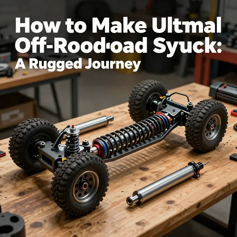
The suspension is more than a set of springs and dampers; it is the living interface between a vehicle and the ground, translating driver intent into controlled motion over radically uneven terrain. In the journey of building an off-road truck, the suspension system stands as the hinge that determines how reliably power, momentum, and steering translate into traction rather than chaos. When you approach it with a holistic mindset, suspension design becomes a synthesis of geometry, material science, and disciplined fabrication. The goal is to keep tire contact with the terrain, maximize wheel articulation, and protect both the chassis and the occupants from harsh impacts. This is not a set of isolated choices but a continuous negotiation among the frame, the wheels, and the weight the truck carries into every obstacle.
Choosing the right suspension architecture begins with the kind of terrain you intend to conquer. Independent suspension, with its ability to let each wheel move without being forced to follow the other, offers superior ride comfort and control on uneven trails. It maintains tire contact more consistently as terrain rises and falls, which translates into more predictable handling and better steering response when you are threading a line through rocks or ruts. On the other hand, a solid axle setup embodies durability and straightforward geometry. It shines in conditions that demand maximum durability and the ability to maintain traction when a wheel drops into a hole or finds a wet, sticky surface. The decision is a balance between the vehicle’s role and how much you value ride quality, articulation, and simplicity under extreme stress. In practice, most purpose-built off-road trucks blend these principles: a robust frame with mounting points that support deep travel, paired with suspension components tuned for the terrain—while avoiding a rigid, unyielding ride that can fracture the chassis or transfer too much energy to the occupants.
Beyond the overarching architecture, the frame itself is the skeleton that carries all suspension forces. The frame should be built from heavy, high-strength materials capable of withstanding the torsion and repeated impacts that off-road driving imposes. The mounting points for control arms, dampers, and springs must be precisely positioned and reinforced. Alignment between these points dictates how the suspension translates wheel movement into steering and traction. If the mounting geometry is off, even small misalignments can precipitate toe drift, uneven tire wear, and degraded control. A well-planned frame design also considers weight distribution. When the chassis carries more weight toward the front, rear suspension must compensate to prevent wheel slip and to preserve stability on descents and while accelerating through rough sections. The aim is a balanced load path that keeps the tires planted without inducing premature wear on bushings or joints.
In selecting the core components, the emphasis falls on strength, adjustability, and resilience. Dampers—commonly referred to as shocks—regulate how springs compress and rebound. For off-road use, the ability to tune damping stiffness is essential, because a single setting rarely suits all terrains. Adjustable dampers enable you to soften the response on rocky trails while firming the control on harder, obstacle-free stretches where precision matters. Springs come in several varieties, with coil springs offering a smooth, progressive response and leaf springs delivering rugged durability in heavy-duty, load-bearing configurations. For high-speed, open-terrain runs, air springs can provide a wide range of lift and spring rates, enabling quick adaptation to changing load and terrain. The springs chosen must harmonize with the dampers to deliver controlled travel, preventing the suspension from bottoming out on a big hit or topping too aggressively when the wheel climbs over a rock or logs. In addition to the primary dampers and springs, sturdy control arms and associated bushings underwrite the geometry that keeps the wheels aligned through extreme articulation. Fabricating or sourcing these arms from thick-walled tubes and robust joints ensures the mechanism can absorb the forces transmitted from the wheel to the frame without bending or binding.
Suspension geometry is a hidden language that governs how the system works. Correct geometry encompasses caster, camber, and toe angles, but it also involves designing for maximum wheel articulation without binding. The goal is to keep the tire’s contact patch as constant as possible across a wide range of wheel travel. Achieving that involves careful attention to anti-squat or anti-dive behavior, track width, and the relationship between the wheel spindle, the control arms, and the mounting brackets to the chassis. When these relationships are optimized, the wheels can articulate deeply without interfering with the drivetrain or with each other. The quality of articulation—the range through which a wheel can move up and down, front to back, without collision—directly informs traction. If a wheel lifts too far, its counterpart may become overloaded, reducing overall grip. The design, therefore, must strike a balance between maximizing travel and maintaining stable geometry under load.
The integration of the suspension with the rest of the vehicle is not a separate step but an ongoing collaboration with the chassis, drivetrain, and even the electrical system. The points where the suspension attaches to the frame often demand reinforcement, especially near areas where engine placement constrains space. These reinforcements transfer the load from a wheel under heavy impact to adjacent frame rails or cross-members, shaping how forces travel through the vehicle. As you reinforce, you must also consider serviceability. Off-road builds are long-term propositions; components will wear, shocks will leak, and bushings will degrade. Providing accessible maintenance paths—clear access to mounting bolts, shielded connectors for sensors and dampers, and sufficient space for routine inspection—saves time and reduces downtime during the life of the truck. The mechanical interface between suspension and chassis must be secure, protected from dust and moisture, and resilient to vibration and heat. Seals and protective boots matter, even if they seem mundane, because neglect here undermines the life of the entire system.
All suspension work hinges on careful component selection and precise fabrication. Precision welding, accurate cutting, and clean fittings matter as much as the suspension choice itself. The frame should be aligned to exact tolerances so that the mounting points mate cleanly with the control arms and dampers. Any misalignment introduces unwanted forces, which can cause accelerated wear, misalignment of wheels, or even premature failure of critical joints. The lesson is simple: the best suspension is useless if its mounting points are poorly positioned or if the frame cannot bear the added stress without flexing in the wrong places. That is why, during fabrication, many builders create mockups or jigs to ensure every part sits in its intended position before final welding creates the permanent structure.
Once the system is assembled, the testing phase begins long before you venture into demanding terrain. Start with torque checks and visual inspections to confirm all fasteners are correctly tightened and all components are seated. Then move to controlled, low-speed testing on flat ground. Listen for grinding or rubbing noises and observe any unusual vibrations. The next stage involves gentle, deliberate trials over increasingly rough surfaces. As you gather data from these runs, you’ll dial in damping settings and spring rates to balance ride comfort with control. The feedback loop is essential: small adjustments to damper pressure, spring pre-load, or mounting positions can translate into meaningful gains in traction and stability. Expect iterations. A suspension system designed for serious off-roading is rarely perfect on the first build; it evolves through testing, data collection, and careful recalibration.
The practical realities of this work extend beyond engineering. It is a craft that demands a readiness to learn, a respect for safety, and a recognition that the vehicle is a complex system—one where power, steering, braking, and suspension must cooperate under a spectrum of loads and surfaces. Those who approach suspension design with a holistic mindset will design around the suspension as a system rather than treating it as a collection of independent parts. They will plan for maintenance, anticipate wear paths, and embed safety margins that protect the occupants even when the truck is pushed to the limits. The process also invites thoughtful realism about costs and time. A robust, well-tuned suspension can consume a substantial portion of the overall build budget and weeks or months of the schedule when you include fabrication, alignment, and iterative testing. But the payoff is measurable: improved traction, more predictable handling in rocks and ruts, and a chassis that endures the punishing realities of off-road travel.
As you advance through the build, you will come to see that the suspension is not merely a technical choice but a philosophy of how a truck meets the ground. It embodies the balance between compliance and rigidity, comfort and control, and lightness and strength. It is the system that translates the driver’s inputs into reliable action, letting you keep the wheels on the ground when the trail throws a surprise. For readers who want to deepen their understanding in parallel with the mechanical work, there is value in exploring how powertrain reliability and maintenance underpin suspension performance. Mastering Diesel Mechanics: Your Step-by-Step Path to Success offers foundational insights into maintaining and optimizing a powertrain, which complements the suspension work well. You can explore that approach here: Mastering Diesel Mechanics: Your Step-by-Step Path to Success.
When the suspension, frame, and drivetrain finally integrate into a coherent whole, you will have created a platform that can confront the most testing terrains with confidence. The road from concept to capable terrain tool is not a straight line; it is a deliberate, iterative path that respects mechanical limits and embraces the learning that comes from testing, observing, and refining. The payoff is a truck not just built to survive off-road passages but to flourish in them, delivering predictable control, durable performance, and the confidence that comes from knowing the backbone beneath you can handle whatever the trail throws your way. For readers seeking broader context on how vehicle dynamics interact with modern simulation and game-engine tools, an external technical resource outlines the sophisticated interactions within a suspension system and vehicle dynamics more broadly: Unreal Engine Advanced Vehicle Documentation can illuminate the engineering principles in a practical, simulation-oriented framework. Unreal Engine Advanced Vehicle Documentation.
Powertrain Precision: Installing the Heart of an Off-Road Truck
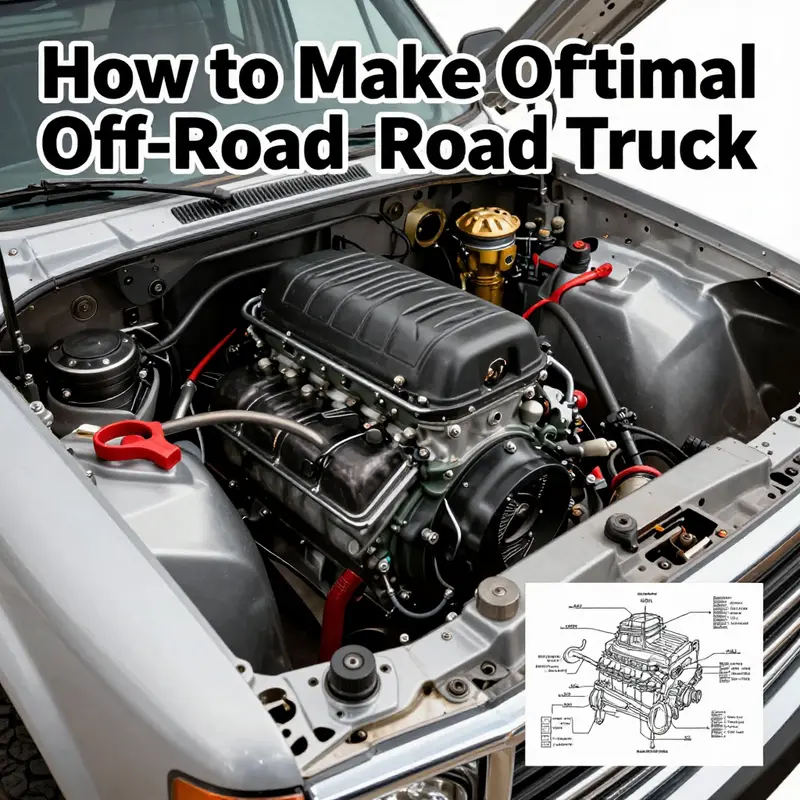
Installing the powertrain is not merely bolting an engine to a frame; it is the moment when a plan becomes a living, controlled force capable of conquering rough terrain. The powertrain, often treated as the heart and lungs of the vehicle, must be positioned, aligned, and integrated with meticulous care. Before any wrench turns, a comprehensive frame inspection sets the stage. Warping, cracks, or unseen stress in the chassis can cascade into misalignment and premature failure once the engine is running and the drivetrain is loaded. With the frame sound, the technician gathers every tool required—torque wrenches, calibrated sockets, alignment bars, jack stands, and a clean workspace. The manufacturer’s service manual becomes the map, spelling the exact torque values, lubrication requirements, and the precise assembly sequence. Skipping this step is inviting trouble, because the powertrain does not forgive sloppy fitment or vague tolerances; it transmits every imperfection through vibrations, heat, and misalignment, amplifying them as hours on rough trails accumulate.
The process begins with the engine and transmission as a unit—an integrated assembly that will live in harmony with the chassis for years. The mounting points along the frame rails must accept high-strength mounts designed to manage torque reaction, engine thrust, and the occasional tailwind of a steep ascent or a sudden drop. Alignment here is everything. The engine’s crankshaft axis must sit in precise relation to the transmission output shaft, and both must be coaxial with the driveshafts once the four-wheel-drive system engages. Small misalignments translate into vibrations, noise, and accelerated wear on the transfer case bearings and transmission bearings. Once alignment is verified, the unit is secured with carefully torqued fasteners that match the spec sheet. It is common to use spacers or shims to fine-tune the engine angle, ensuring the crank and the transmission flange sit square to the transfer case input. This is not cosmetic; it prevents premature clutch wear, worn input shafts, and uneven torque transfer that can rattle the chassis at high speed on rocky trails.
With the engine and transmission anchored, the transfer case follows as the next critical link. The transfer case acts as the bridge between the engine’s power and the front and rear driveshafts. Its installation is a study in precision: the output flange must line up exactly with the transmission’s output, and the drive gear must sit into its correct mesh depth without binding front-to-rear. Lubrication is not an afterthought. The correct oil type and quantity must be present to protect the differential gears and the planetary gears inside the case, especially under the stress of mud, sand, or rock impacts where heat builds quickly. During this stage, alignment tools help ensure the transfer case sits parallel to the frame, avoiding a subtle yaw that will later translate into uneven four-wheel-drive engagement and excessive driveshaft angles. In practice, many builders spend extra time verifying that the transfer case is mated without lean to either side, because a slight tilt can alter U-joint angles and create vibrations that only reveal themselves during off-road testing.
The driveshafts themselves demand equal attention. Their length, balance, and angular relationships with the transfer case and differentials define how smoothly power is transmitted to the wheels. Proper driveshaft installation requires flawless alignment of the universal joints, since misaligned U-joint angles cause vibration, heat, and accelerated joint wear. The front and rear shafts must neither be too long nor too short; their angles should remain within the crossjoint’s favorable operating window across the engine’s torque envelope. It is also essential to confirm that the flange sockets and yokes are clean, that grease fittings are accessible, and that the joints are properly lubricated before assembly. If a shaft is slightly out of balance, it can cause high-frequency vibrations that magnify at speed on uneven surfaces—a compounding problem when the truck is driven into a boulder field or a dune wash.
Differentials bookend the drivetrain as the final, critical interface between the power and the rotating wheels. The front and rear differentials must slide into their housings with the correct pinion depth and bearing preload as specified by the gear manufacturer. Differential installation is as much about sealing as it is about mesh. The preload and backlash settings determine how quietly the gears engage under load and how long the set remains reliable under stress. A sloppy seal or an inconspicuous leak now can become a major oil loss in the desert or a muddy river crossing. The seals must be seated correctly, and the gear oil must be the type and quantity called for by the design. As the assembly progresses, checks for binding, unusual resistance, or misalignment are essential. If the gears do not mesh cleanly, the resulting noise, heat, and wear will be amplified once the truck encounters the first hard landing or the first steep climb. This is where patience pays off; a careful, measured approach to the differential installation sets the stage for decades of dependable performance in harsh environments.
At this stage, the story becomes a synthesis. The frame rails, the engine and transmission assembly, the transfer case, driveshafts, and differentials must all come into alignment as a system. The process is not merely about turning bolts; it is about engineering the drivetrain so that every component shares the same cadence under load. The alignment checks extend to the crossmembers and mounts: the engine torque is distributed into the frame with predictable stiffness, the drivetrain angles remain within a safe range across articulation, and the four-wheel-drive system engages without clunking or binding. The torque values from the service manual become the conductor’s score, guiding each fastener to its rightful clamp load. In practice, this means double-checking every fastener after a short test run, re-tightening where necessary, and re-checking for interference with the exhaust, heat shields, and the suspension geometry.
The testing phase is not a ceremonial finale; it is an essential, iterative discipline. After the initial assembly, a careful, staged start-up reveals any leaks, misalignments, or binding that could compromise safety. A short, controlled run on flat ground allows the operator to listen for odd noises, observe vibrations, and verify the feel of the clutch engagement or automatic transmission shifts. The next step is a cautious, low-speed evaluation of the four-wheel-drive engagement—both when moving and when stationary. Any clunk, grind, or hesitation is a red flag that requires immediate investigation. Only after these checks show a clean, quiet, and linear response should the vehicle be subjected to more challenging terrain. The moment when you cautiously traverse a rock alley or a steep slope and feel each axle take a controlled bite is the payoff of meticulous, patient work. Failures in this phase stem not from one ferocious bolt but from small deviations collected over hours of fitting, aligning, and testing—deviations that compound when the vehicle is loaded with weight, fuel, and gear on a trail under external stress.
A project of this scale demands more than mechanical skill; it requires a disciplined, iterative mindset. The powertrain installation is the culmination of precise planning, exacting assembly, and rigorous testing. It is where the theoretical plans of CAD drawings meet the realities of metal, heat, and torque. Mastery in this phase does not arise from brute force but from careful measurement, repeatable procedures, and the discipline to document and verify every step. For readers seeking deeper understanding of diesel-based powertrains and the broader mechanics of engine behavior, a respected resource like the Mastering Diesel Mechanics guide offers a structured approach to fundamentals and troubleshooting. This kind of reference underscores the truth that powertrain work blends art and science: the art of fitting components together in harmony and the science of understanding tolerances, lubricants, and load paths. For further study, you can explore this comprehensive pathway: Mastering Diesel Mechanics: Your Step-by-Step Path to Success. As always, safety remains paramount. The powertrain carries significant mass and potent energy; any misstep can lead to injury or costly damage. If uncertainty lingers, pausing to consult a professional or taking a formal course can be a decisive investment in long-term reliability and off-road safety.
External resources can broaden understanding beyond the shop floor. For engineers and enthusiasts seeking broader context on powertrain fundamentals, reputable external references can be invaluable. See the engineering literature and standards maintained by SAE International for extensive guidance on propulsion systems, lubrication regimes, and drivetrain geometry. External resource: https://www.sae.org/.
Ground Contact Engineered: Tires, Wheels, and Fitment Mastery for Your Off-Road Truck Build
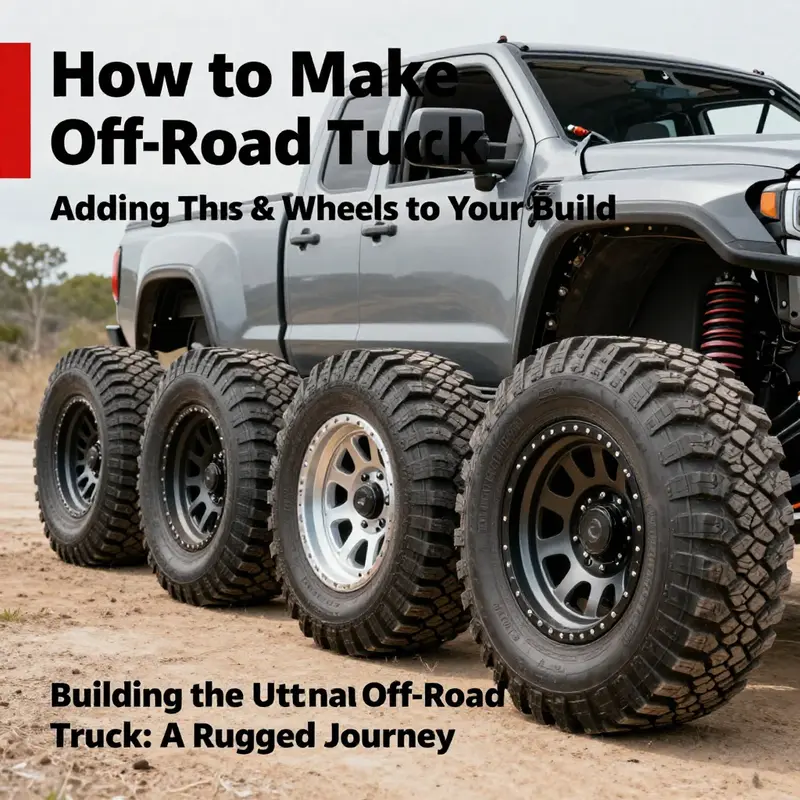
Tires and wheels sit at the intersection of traction, durability, and ride quality. They are the most visible part of an off-road build, yet their impact runs deeper than looks. The sprung and unsprung mass, the torsional forces from a rough trail, and the drivetrain’s response to larger rolling contact all hinge on the choices you make here. In shaping an off-road truck, you don’t just swap parts; you craft a system that translates power into controlled momentum across stubborn terrain. That starts with tire size, tread design, wheel construction, and the exact way those two components integrate with your chassis, suspension, and braking hardware. You can engineer for climb and rock contact, or for desert speed and stability; the options you select must align with your vision, your terrain, and your mechanical tolerance for trade-offs in comfort and wear. For many builders, this is the gateway where ambition meets practical constraint, where a misfit tire can ruin a trail day as quickly as a torn belt or broken bead could end a run. The planning phase here is as important as any weld in a frame because it dictates steering effort, gearing perception, vibration, and the risks you’ll manage on every descent and crossing. A thoughtful approach begins with compatibility checks. Size is more than a number on a tire sidewall; it’s a major variable that affects clearance, steering geometry, and the suspension’s travel envelope. Larger tires need room to spin freely without rubbing against fenders, control arms, or the brake rotors at full lock or full droop. Consult fitment guides, but also trust your own measurements. Your chassis geometry, coil or leaf spring travel, and any lift or fender modifications will determine the real-world limits of your wheel and tire combination. As you plan, decide on the tire type that best matches your use case. An all-terrain pattern can offer steadier highway behavior and predictable wear, while mud-terrain tires deliver maximum grip in slick conditions and heavy obstacles. However, MTs typically add rolling resistance and can alter fuel economy and noise. If your build is leaning toward rock crawling or extreme dirt trails, you’ll likely lean toward tougher sidewalls and aggressive shoulders. The wheel itself must be up to the task. Off-road wheels demand strength, with forged or high-grade cast aluminum options that resist bending under side impact and grip the bead securely during low-pressure runs. The wheel’s diameter, width, and offset are a trio of variables that influence caliper clearance, brake line routing, and steering leverage. Off-road fitment must account for backspacing and offset to maintain proper scrub radius, which affects steering feel and the tire’s contact patch during articulation. You will also consider the bolt pattern and hub bore; mismatches here can invite vibration, wobble, and long-term hub wear. The fitment conversation would be incomplete without addressing tire pressures. On rocky trails or in mud, running lower pressures increases the tire’s footprint and consolidation on uneven surfaces, improving grip. Yet you must avoid going so soft that bead seating becomes unstable or the tire bead breaks away from the rim during a flex cycle. A practical approach blends field experience with manufacturers’ guidelines; start conservative, then tune pressure as you gain trail data. The discussion about wheels should fold in the important topic of wheel studs and lug nuts. With larger, heavier tires increasing the rotational load, you want robust fasteners with correct thread engagement and seat design. Anti-seize compounds on the lug threads can ease future removal and prevent corrosion that can seize bolts in muddy, corrosive environments. These are small details, but they pay off every time you rotate tires or perform maintenance after a long trip through harsh terrain. If you’re seeking deeper mechanical grounding as you navigate these decisions, consider resources that tackle powertrain and mechanical fundamentals in depth. For a broader context on integrating engine work with a broader build, you can explore Mastering Diesel Mechanics: Your Step-by-Step Path to Success. This helps ground your tire and wheel decisions within the bloodstream of your truck’s overall capability. While tire choice is about grip, it’s also about cadence—how that grip translates into forward momentum, braking control, and the ability to place the truck where you want it on the trail. The tire’s footprint interacts with the suspension’s geometry to determine how the vehicle attacks obstacles. A well-chosen tire and wheel package keeps your steering geometry stable through articulation and reduces the likelihood of sudden, unpredictable contact with rocks or ruts. Beyond the math of fitment and the aesthetics of a large, aggressive tire, there is the matter of safety and code compliance. The vehicle must remain controllable at speed down a long descent, with predictable braking and steering response. You’ll balance the increased unsprung mass of larger tires with a suspension setup that can accommodate larger travel and stiffer dampers when needed. This harmony between tires, wheels, and the rest of the system is what separates a build that looks capable from one that actually performs under load. The practical steps of installing and verifying your tire and wheel setup are straightforward in sequence, but they deserve careful attention. Begin with a thorough safety check: park on level ground, engage the parking brake, and support the vehicle securely on jack stands at the manufacturer’s recommended points. Remove the old assemblies with a crisscross torque pattern to help the lug nuts come off evenly, then inspect the hub surface for corrosion or damage that could hamper proper seating of the new wheel. Clean the hub face and axle shoulder to ensure a clean mating surface. Align the new wheel with the hub, ensuring the holes line up and the wheel sits flush against the hub. Lightly thread the lug bolts by hand and then snug them in a star pattern to seat the wheel. Lower the vehicle and torque the lug nuts to the manufacturer’s spec with a calibrated torque wrench. Recheck after a short break-in and again after 50–100 miles; this helps account for any slight settling that occurs as the wheel’s assembly mates with the new tire and rim. Inflate to the tire’s recommended pressure, recognizing that for off-road scenarios you can reduce pressure within safe limits to gain flotation and traction on soft surfaces; avoid falling below the tire’s minimum recommended pressure. After installation, you’ll want to verify clearances during full steering lock, full droop, and during cornering. Check for rubbing on fender lips, control arms, or brake components, and ensure all calipers and brake lines are clear of the wheel’s rotation arc. If you’re moving to a larger diameter, you’ll almost certainly need a realignment and a balance. A proper four-wheel alignment makes sense after any major wheel size change, helping to ensure tire wear remains even and that handling remains predictable across varied terrain. Balancing should accompany the alignment, given that the new mass distribution can introduce vibrations at certain speeds. On the maintenance side, carry spare lug nuts and studs, a torque wrench, and a small amount of anti-seize for future adjustments. A few pro tips can save you from headaches down the road. Anti-seize on lug threads reduces the risk of seizure when you later remove the wheel for service. Upgrading to higher-strength lug nuts can add security for aggressive travels through rough environments. Also, track tire aging; even new tires have a shelf life—avoid tires older than five years from the manufacture date. Finally, monitor wear patterns and component health. Larger, heavier tires place extra demand on U-joints, CV joints, and axles, so inspect these parts more frequently after the upgrade and during regular maintenance cycles.
The result of all this planning and careful execution is more than just a bigger footprint. It’s improved traction in tricky situations, more dependable braking at the end of steep descents, and a vehicle that can place itself on the trail rather than drift off into the bushes after a misstep. If your goal is to build a truck that can handle muddy bogs, desert washes, and jagged rock, the tire and wheel strategy you choose now shapes your entire ride quality and reliability later. It is not merely a cosmetic upgrade; it is a functional design decision that affects steering feedback, throttle modulation, and the confidence you feel when you throttle into a challenging section. When you’re ready to extend your knowledge further, remember that the wheel and tire domain sits in the broader ecosystem of your off-road truck build—where engine torque, transmission ratios, suspension travel, and drivetrain gearing all interact with how contact is made with the ground. The better the fit, the more predictable the vehicle becomes under load, and the more capable you become at reading terrain and choosing the best line. External reference: RockKrawler fitment guide provides compatibility charts, torque specs, and fitment videos to help verify that your chosen tires and wheels will clear everything from brake calipers to inner fenders on common platforms. https://www.rockkrawler.com/fitment-guide
Final thoughts
Crafting your own off-road truck is not just about assembling parts; it’s a labor of love that combines creativity, engineering, and sheer determination. Each chapter of this journey equips you with essential skills and knowledge that extend beyond the garage, fostering a deeper appreciation for the art of mechanical design. With every bolt tightened and every feature optimized, you prepare to hit the trails with confidence. Your ultimate off-road truck, a testament to your vision and hard work, awaits—ready to conquer any terrain. Embrace the challenges that arise, relish the triumphs, and most importantly, enjoy the adventure that lies ahead!